A warped approach to circuits

What happens if you have to make a lot of crossovers on a circuit board? For example, here is a printed circuit board that connects pins 1 to 10 in a randomly chosen order. In this layout, finished by a person after the autorouter gave up, you have to drill 14 holes, spend time and create dust.
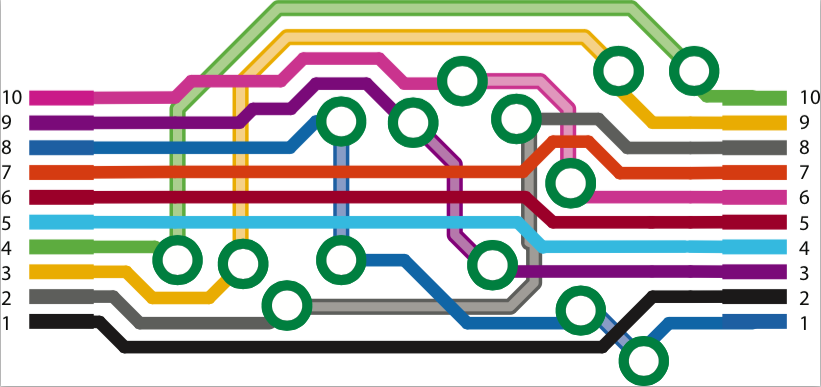
2 layer printed circut board sends pins 1-10 from the left to different pins on the right side.
2 layer printed circuit board sends pins 1-10 from the left to different pins on the right side.

Keeping in mind that our group is working on unconventional electronics, could a woven circuit do better? Woven items are made of crossovers between warp and weft threads. Looking at the problem of how you would bring 10 connectors from right to left on a circuit, crossovers are painless if the wires are insulated, but corners are harder because they involve soldering and cutting. Here is an autorouter in action that draws the same circuit as the PCB, attempts to minimize corners and doesn’t get stuck. (MATLAB code and 100-pin example after the jump).

Continue reading “A warped approach to circuits”

Update: A blistering summer

Jeremy at FirstBuild pulled a couple of vacuum molds for the light diffuser on the Trilife cellular computing project. Here’s a video showing a softened thick PETG sheet forming over the triangular mold:

Next you let it cool, then you tap it to knock it off, and then pull the mold down as in this video:

Because the minimum sheet size is 2×2 feet, there’s a lot of extra material to chop off, and it is 1/16″ thick. Imagine opening one of the worst blister-packs ever, except that instead of the USB stick you just bought, the prize is the blister itself. We used shears for the first one, and plan on a hot wire or laser cutter for more automation later. It will also get some paint or some sandblasting to diffuse the light.

Pop up 3D structures printed on stretched fabric


Amy discovered some good settings for getting 3D printed materials to stick to spandex. We can print flat, thin structures and have them control how the fabric bends and folds. We can also use the fabric’s tension to warp them into 3D shapes. This concept has a lot in common with our microscale pop-up structures. But why would you want to do this?

  • Since 3D printing time scales with volume, it can be much faster to produce a pop-up structure from a thin sheet than to 3D print it directly.
  • Integrating hard and soft materials is going to be key to making soft robots that contain electronic and mechanical structures, at least in the near future. For instance, even though robots are getting tentacles for arms, their brains are still made from brittle silicon-based computer chips.
  • Fabrics have diverse properties: they’re flexible and can contain fiber optics, conductive wires, tubes for fluids and gases, stretchy threads, shape memory wires…the list goes well beyond what we can get from 3D printed materials these days. Let’s combine these materials with the fast customization of 3D printing!
  • Continue reading “Pop up 3D structures printed on stretched fabric”

    Recent Student Deeds

    StudentDoingsSpring15

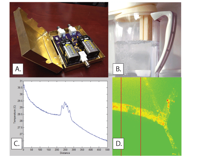
    Four independent study students finished projects in Spring 2015. (A) Tayce Lassiter tested a differential impedance circuit on paper microfluidics, and also built a metal case to keep out noise.(B) Juan Espinosa, our GE Edison student, carried on an embedded systems project on a self-filling water pitcher for the fridge. He also motivated the ECE 412 students at the start of final projects season with a guest lecture. Here is the new ECE412 final projects blog. (C) Thomas Johnson figured out how to get the QFI thermal imager talking to MATLAB so we can generate plots and charts of thermal data in our nanoparticle heating projects. (D) Thomas worked with samples from Caleb Sheehan, who translated our nanoparticle flow patterning method from silicon to glass substrates that had better thermal insulation for local temperature mapping.

    Cyber plumbing with ANSYS Fluent

    Illustration of pore showing flow vectors
    Polarized metal pore with fluid velocity vectors

    Flows can be driven using metallized surfaces in an electric field. This research area is called “induced charge electrokinetics.” It originated in the world of metal colloids, saw some applications in microfluidics in the 90s, and has seen more intense research over the past 10 years. This paper is a good introduction to flows around metal posts in an electric field.
    We can measure ICEO effects with video microscopy to track high speed swirling tracer particles. We can also simulate the effects, and one method is to take a commercial computational fluid dynamics (CFD) package to a small size scale that most tutorials don’t cover. Here is our pdf tutorial with links to videos on using ANSYS Fluent to generate microscale flow fields from a given wall velocity, creating images like the fluid velocity vectors shown in the image above.